The General Idea
My goal was to create a virtual pinball machine. I wanted to create as much as possible of that by myself, which includes the case, the board, the game and all of the assets used in the game itself. For this I used the softwares Tinkercad, 3Ds Max and Unity.
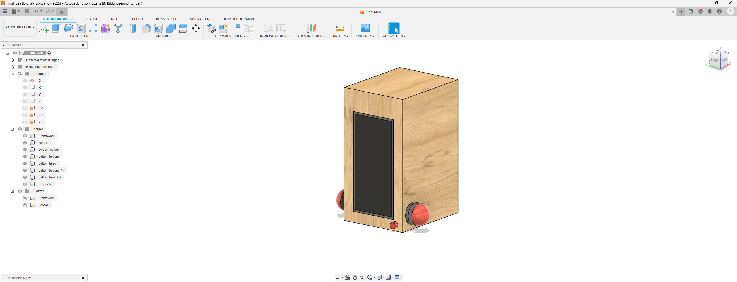
Step 1: Initial Project Idea & Fusion Model
The general idea of my final project was to create a small pinball arcade machine with a virtual screen to simulate the game. The idea is that the player can press physical buttons on the side of the machine to control the pins within the virtual game.
For this to work I need to code my own version of pinball, probably in a game engine like Unity. The build of this game now has to be hooked up to a panel which can accept the inputs of the physical buttons. The input will need to proccess instantly to give the player a submersive gaming experience.
In summary, the project is going to need a pinball game build, a machine which is able to run the game build, a screen to display the game, buttons, an input reader and wood for the framework.
 Download Initial Fusion Files (.f3d)
Step 2: Updated model of the final project
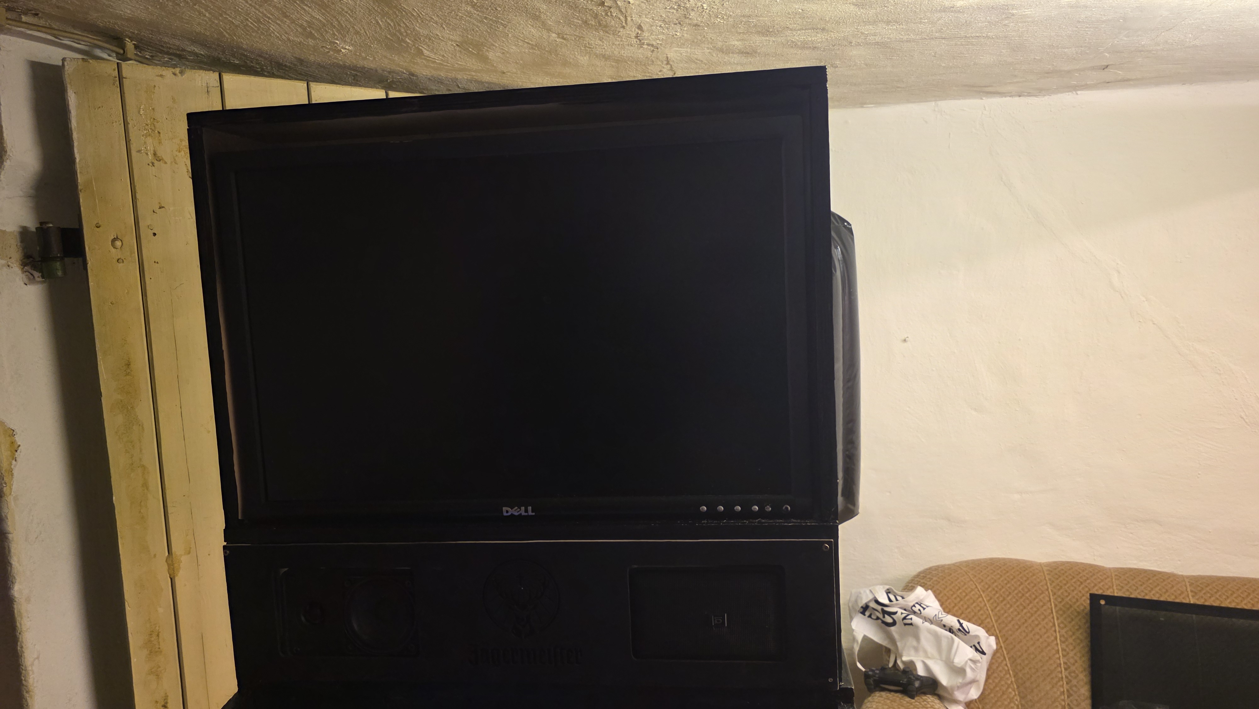
When starting to work on the final project I needed to adapt my ideas for it a little bit, because of the budget. I knew from the start that this project is going to be expensive, which is why I was looking for the most expensive stuff I needed, which was the TV, on reseller websites like eBay. Because of this however the scale of the project drastically changed.
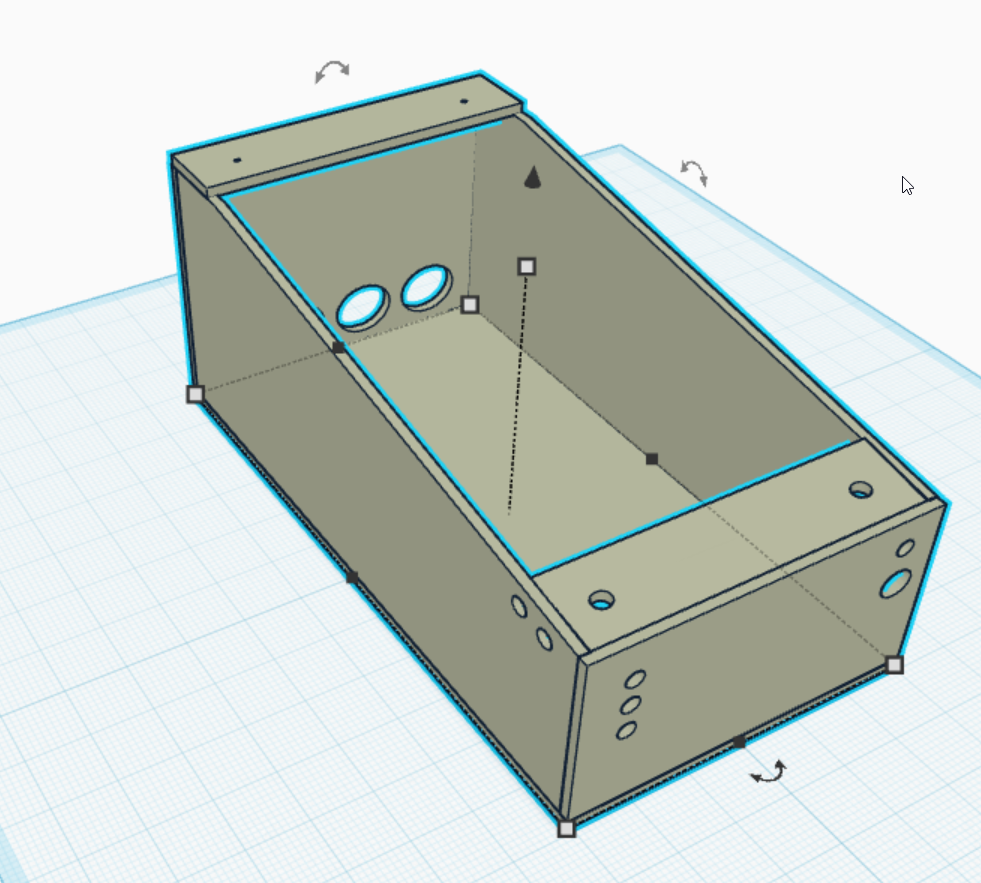
As you can see above, the old fusion project looks a lot different compared to the final project. This is because I did not know exactly what will be needed at the time of creating this first project concept. Because of this I created a new one, which can be seen below. This project was not created in Fusion, but with Tinkercad, because I personally did not really like using Fusion.
In pictures below you can see the 3D schematic I created for the wooden case of the flipper. This was a crucial part in the project, as it had to be big enough to be able to house my computer underneath the big screen on top, but also stable enough to support the combined weight of both the TV and the PC.
 Download Final Project (Tinkercad Files)
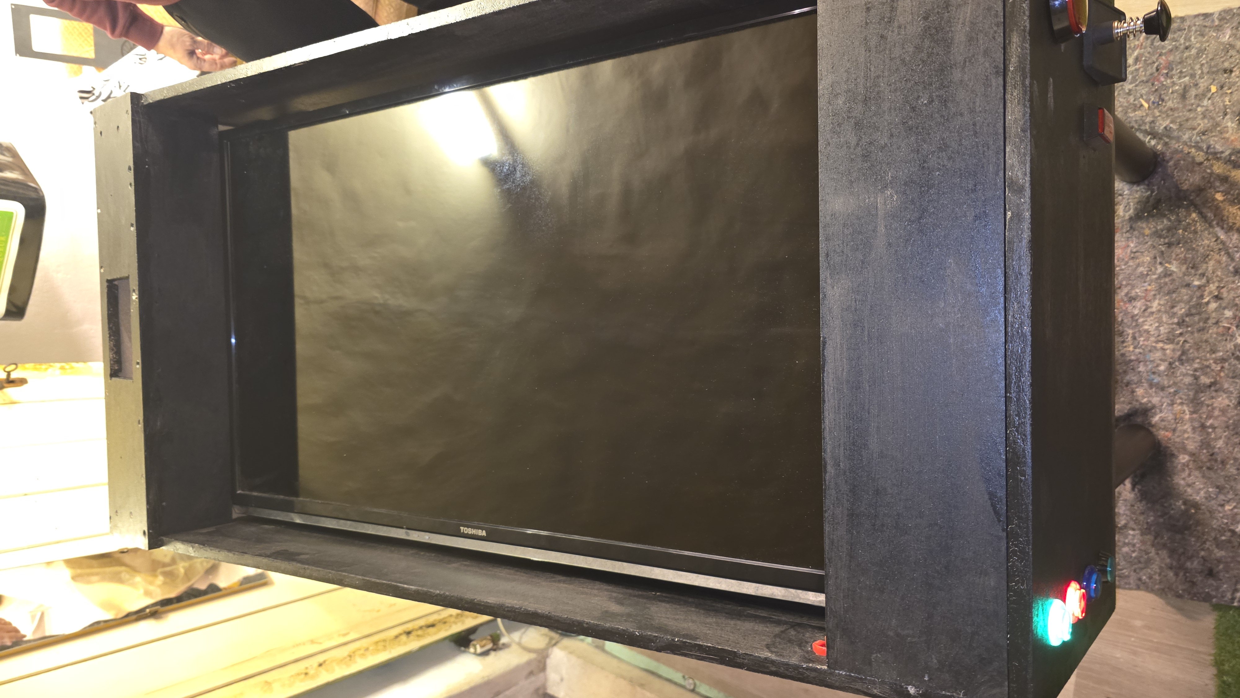
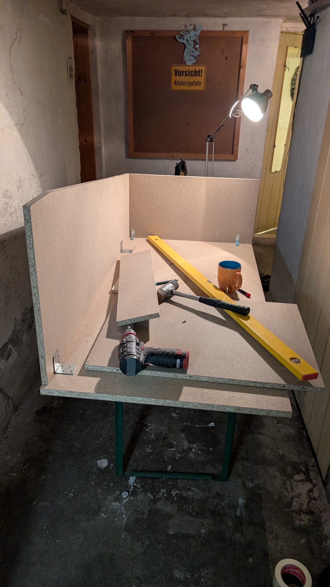
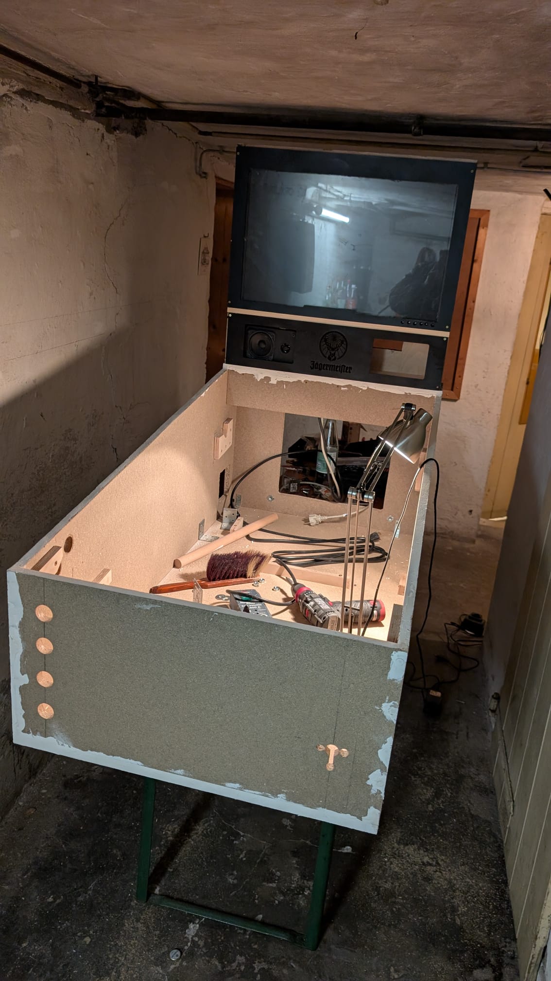
Step 3: The construction of the wooden Case
After completing the schematic it was time to start the construction of the wooden case. Because of the schematic I created in the exact measurements I could look for wood in the hardware store. Afterwards I used a small saw to create the slopes in the wooden case.
I also used this to create the holes for the buttons. These needed to fit in perfectly so there was no room for error. Luckily the exact measurements of the buttons are listed in the shop, which made this process a lot easier. I used angle connectors to screw the different sides of the case together.
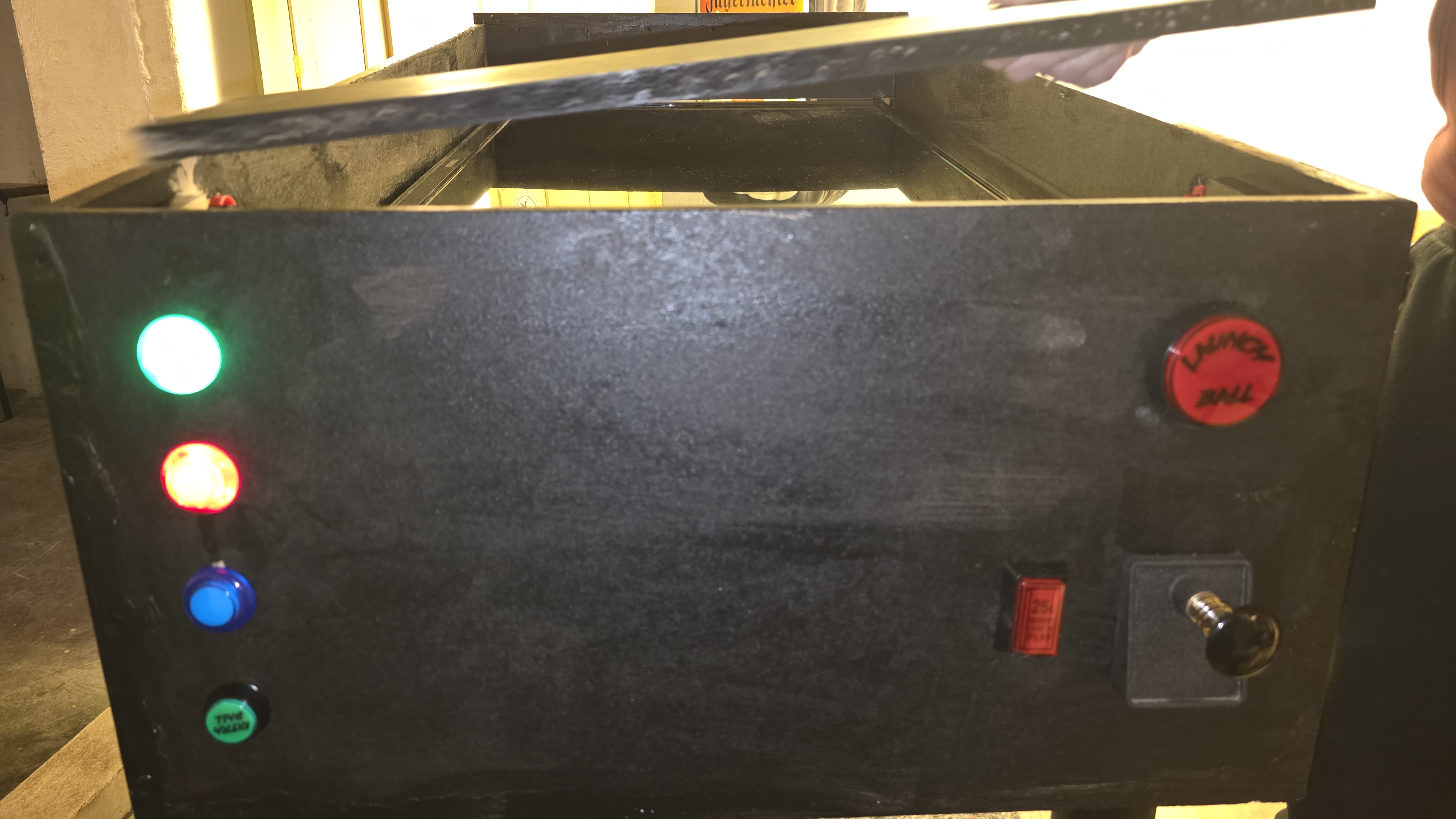
Step 4: Finishing the case and putting in the button holes
As you can see the button layout differs a little bit from the layout originally planned. This is because I decided to buy a plunger instead of just using a button for the ball launch mechanism.
You can also see that there is a second screen ontop of the wooden case. This was supposed to show the score of the flipper game. However I was not able to complete it in time which is why it does not work in the final version of the virtual pinball table.
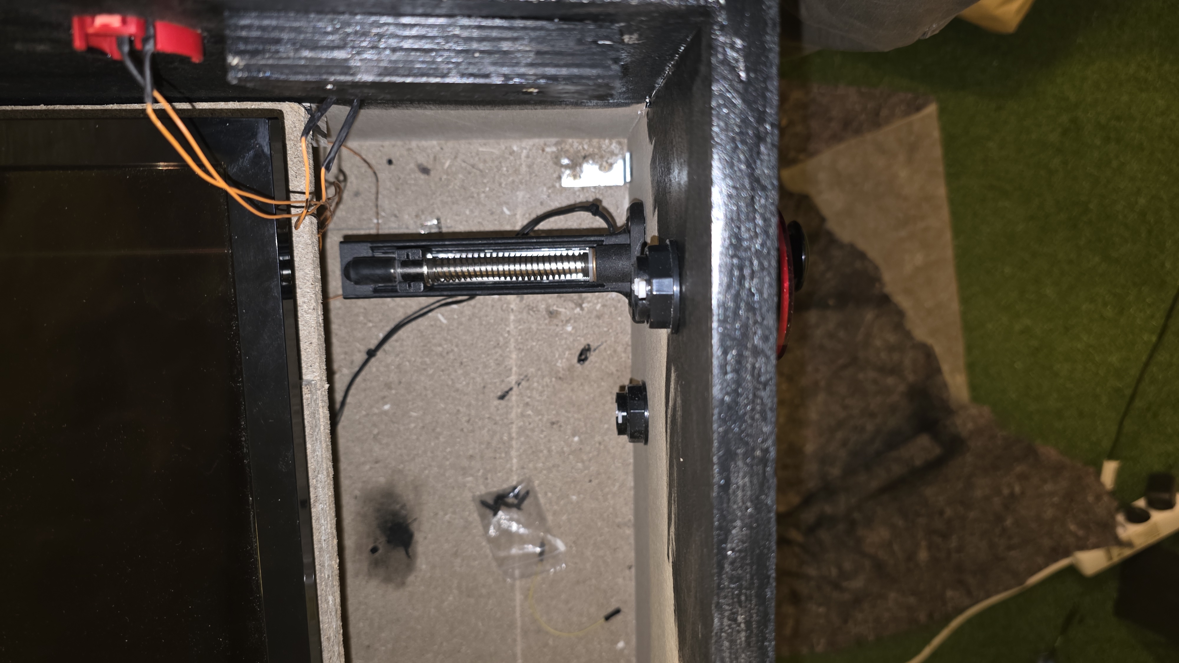
Step 5: The Plunger
The digital plunger button is a classic piece of pinball machines. It simulates how the player must pull on a physical plunger for the ball to launch. In my case it kind of works as a potentiometer, as I will later show when talking about the code. It is wired to the process control board and uses the only analog pin of my project.
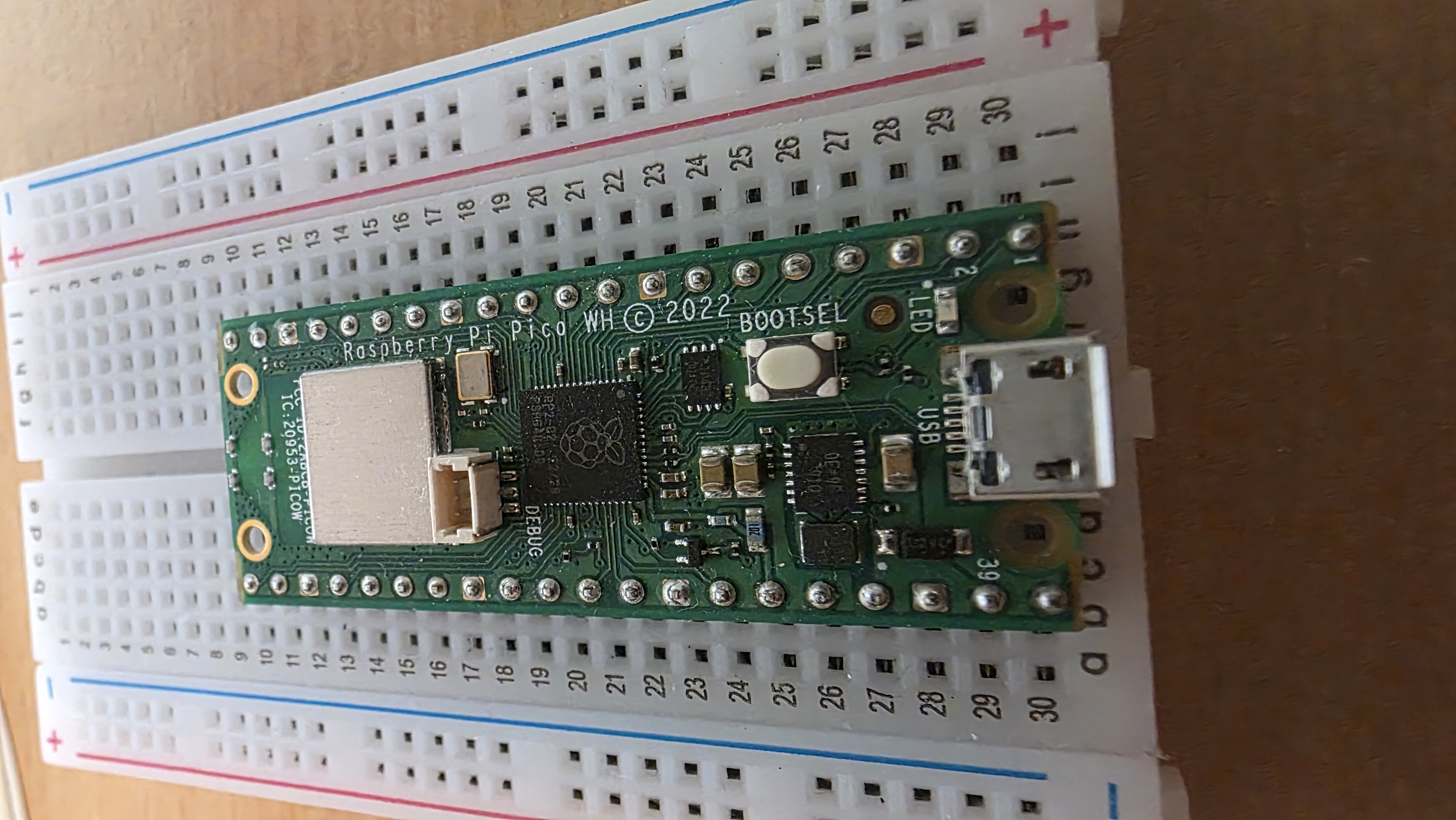
Step 6: The decision on the microcontroller
For my project to work I needed to somehow make the buttons of the flipper communicate with my PC. I learned that I would need a microcontroller for this. After careful consideration I decided to use the Raspberry Pi Pico microcontroller. The Pi pico can be connected to the pc using a USB cable and has a lot of digital, as well as enough analog pins for my project.
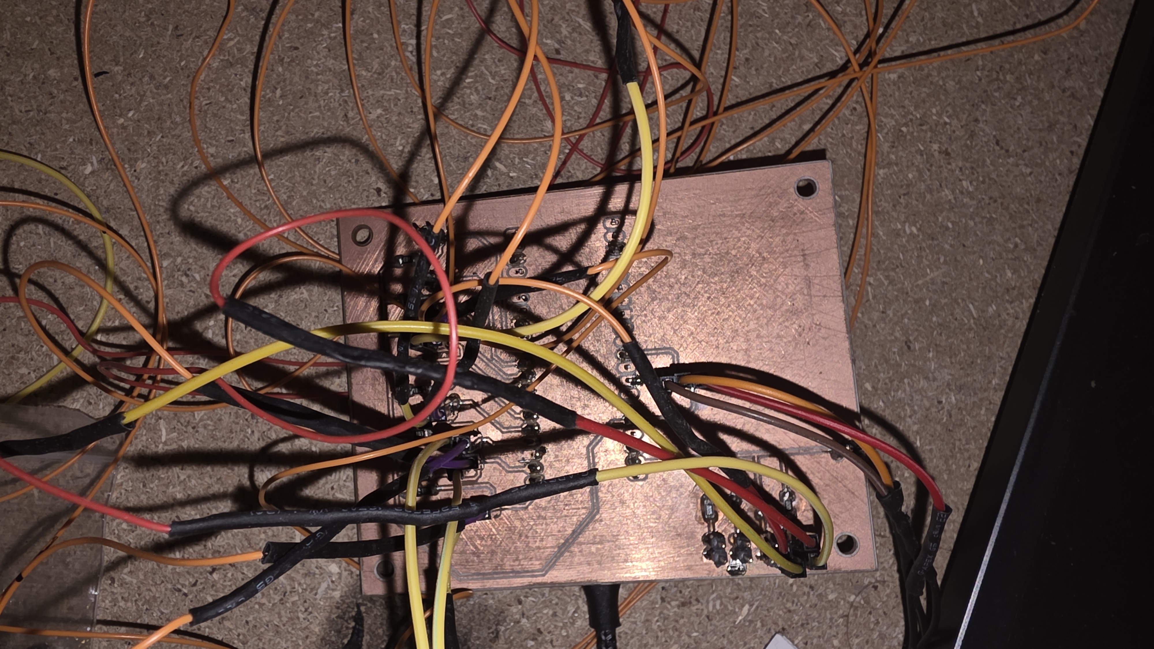
Step 7: The creation of the PCB
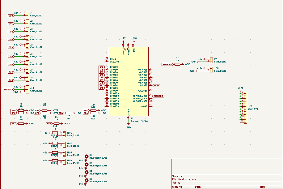
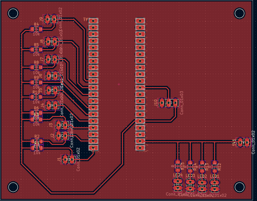
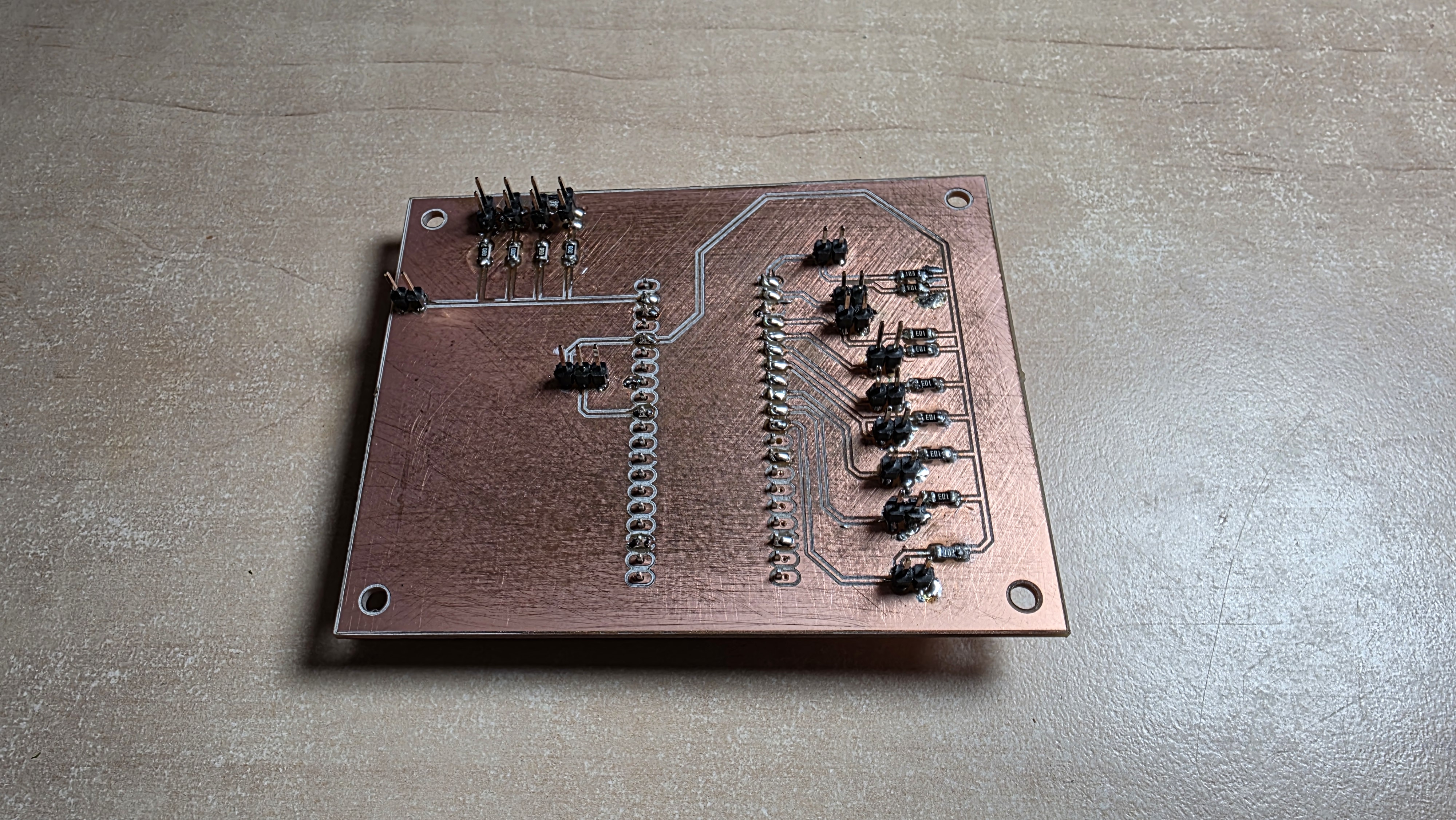
The entire creation of the PCB can be seen at Week 8: Electronics Design. Here are the pictures of the final result:
Schematic
Board Layout
Milled Board
Step 8: Creating the first prototype
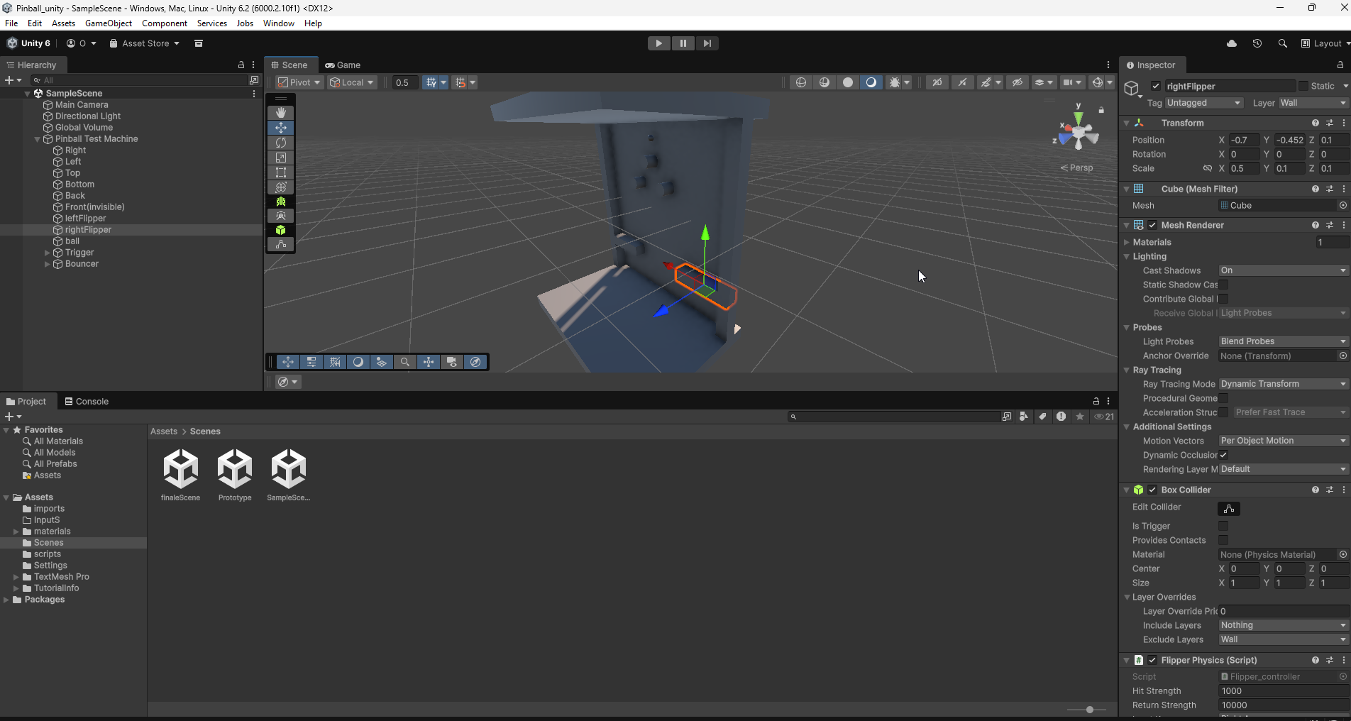
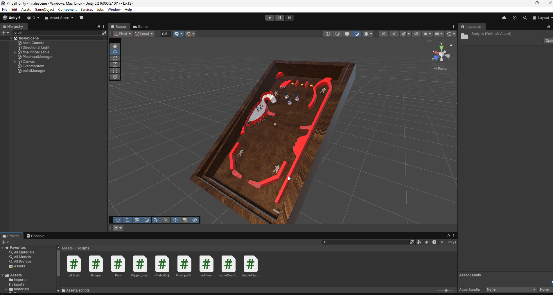
After assembling the PCB I started with the creation of the Unity project. Even though I have worked with Unity a lot in the past I was not completely sure how I wanted to start this project, as I have never created something like a pinball game. Before starting to model the assets or program I needed to think about what is important in pinball games.
My conclusion was that the most important parts are not the visuals but physics. Unity has a build in physics engine, however I it will still take a bit of trial and error to get the physics to work right. Before creating something fancy, I had to get the basics to work. For this I created a small prototype out of 3D objects in unity. These already come with a box collider, so I can use them as walls and ground.
I also added a sphere which will be used as the ball. The sphere is the only object of all of them that is not set to kinematic, which means it will be affected by physics and fall as soon as the game is started. Afterwards scripts were added to the different parts, however I will not explain them in detail here as they are very early versions and it makes more sense to show the final ones later. With that I have created the first very rudimentary but working pinball machine game. This prototype is part of the final Unity project and can be found in the template scene. I will add the Unity file at the end of this blog.
Step 9: Creating an advanced prototype Layout
As you have seen in the protype above it is still limited. Even though the basics work, it is not possible to advance the creation of the scripts needed for the final project with this limited design. This is why I decided to create a new layout in 3DS Max. This was the first time I have ever created my own 3D assets and imported them into Unity, which was a really interesting learning experience.
Step 10: Using the new prototype in Unity
After creating this new asset it was time to import it into Unity. The new asset allowed me to work on features such as the launch mechanic, the scoreboard, objects that give the player points when the ball rolls over them, as well as objects that hide for a few seconds after being hit.
I also tested a few bounciness values for the ball until I found one that looked natural. I also changed the script of the two triggers on the side, so that the rotation of them feels a lot more like it does in classic virtual pinball games. To achieve this I used Unitys hinge joint mechanic.
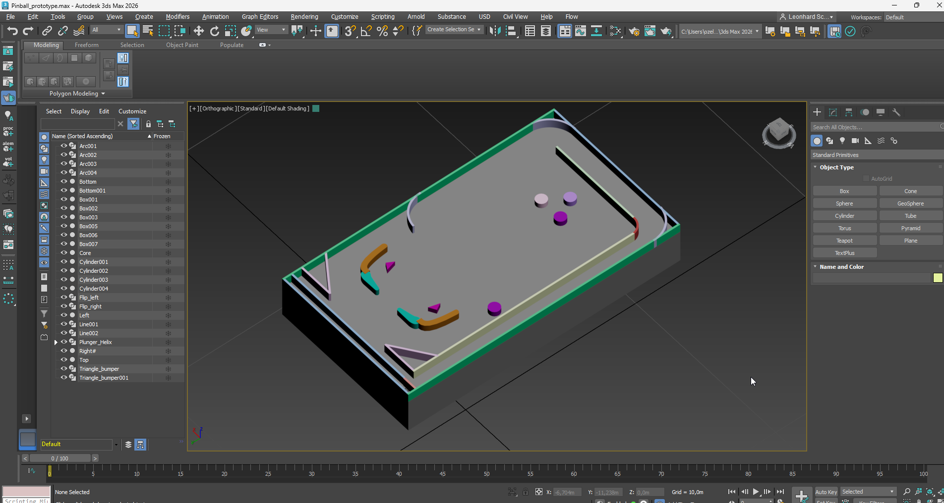
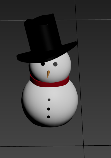
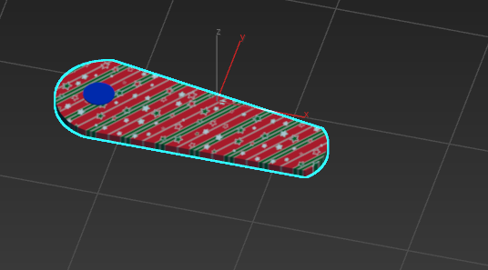
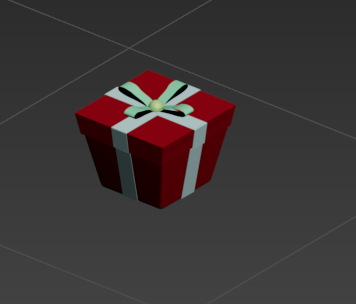
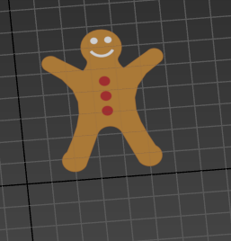
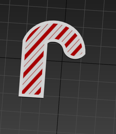
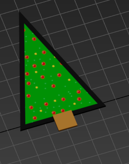
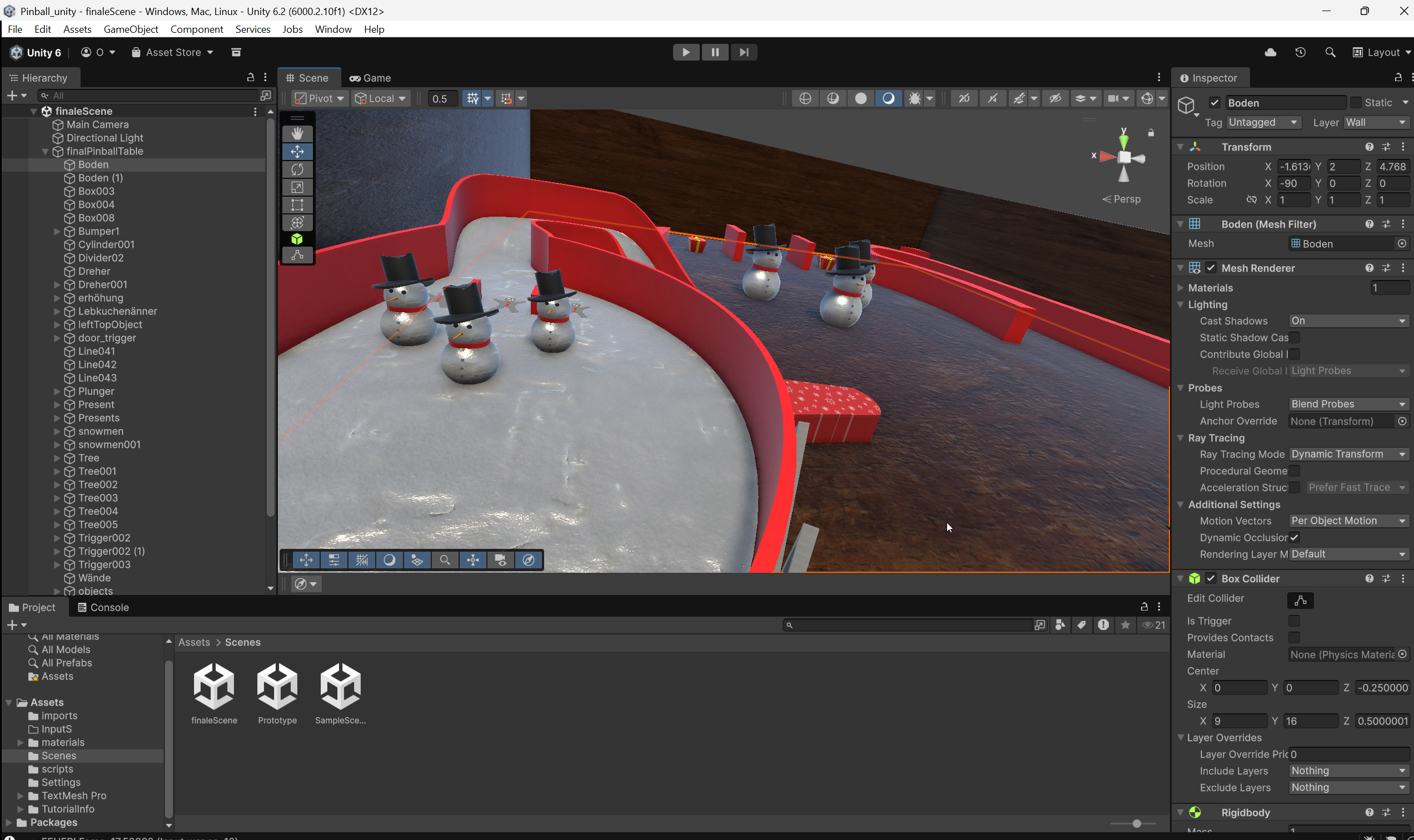
Step 11: Creating assets in 3DS Max
With all of the functions of the pinball machine working it was time to create the assets I wanted to use in the final project. I decided to go for a Christmas themed pinball machine. Here are all of the created assets, as well as the files to download them:
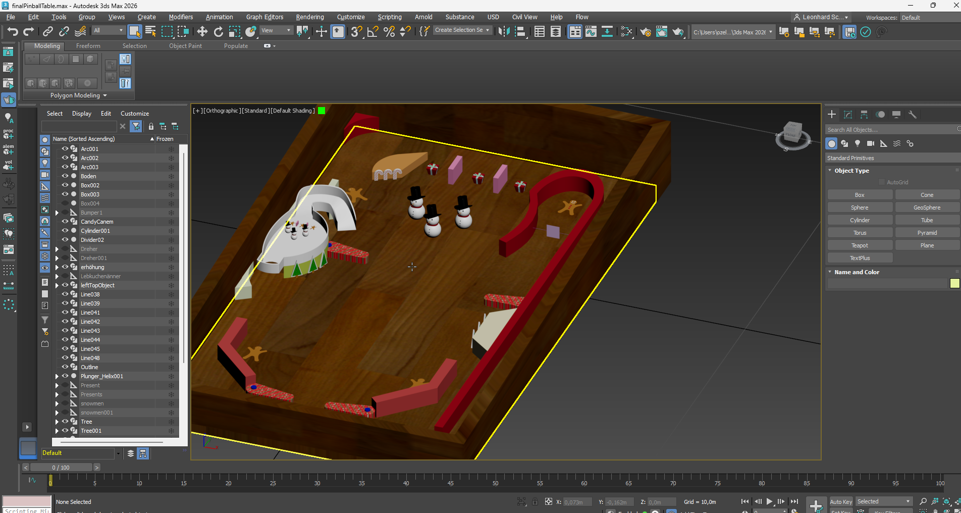
Step 12: Assembling the final pinball table layout
After creating all of the assets it was time to decide if it is better to make one giant asset in 3DS Max out of all of them or if it is better to import all of them into Unity and assemble them there. I decided to do it in 3DS Max because of the easier alignment tools.
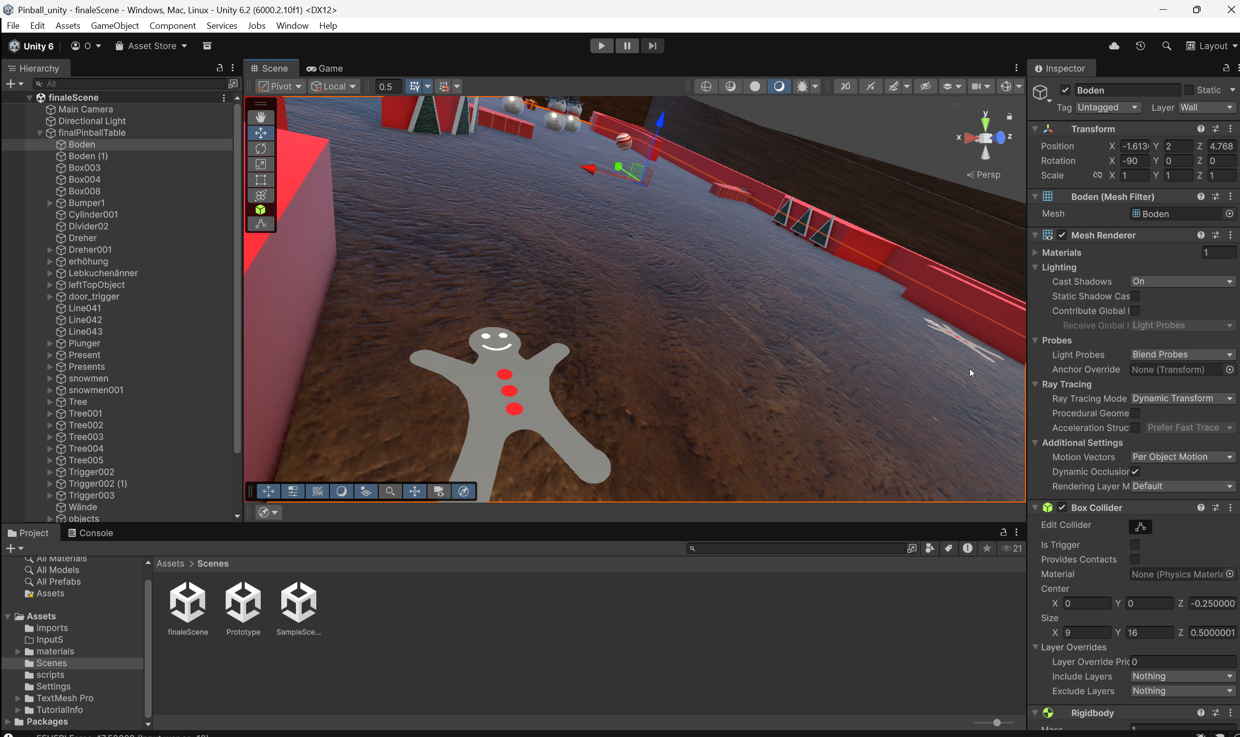
Step 13: Putting it all together in Unity
Now we have all the parts. After importing the final pinball table layout the only thing left was setting the physics to the right parameters. This proved to be a little bit more difficult than the last few times as I had to play with scaling some parts up and some down for the table layout to work, which in return meant I had some performance issues because of the huge mesh colliders I created. However after a bit of trial and error it worked and the final table layout is finished.
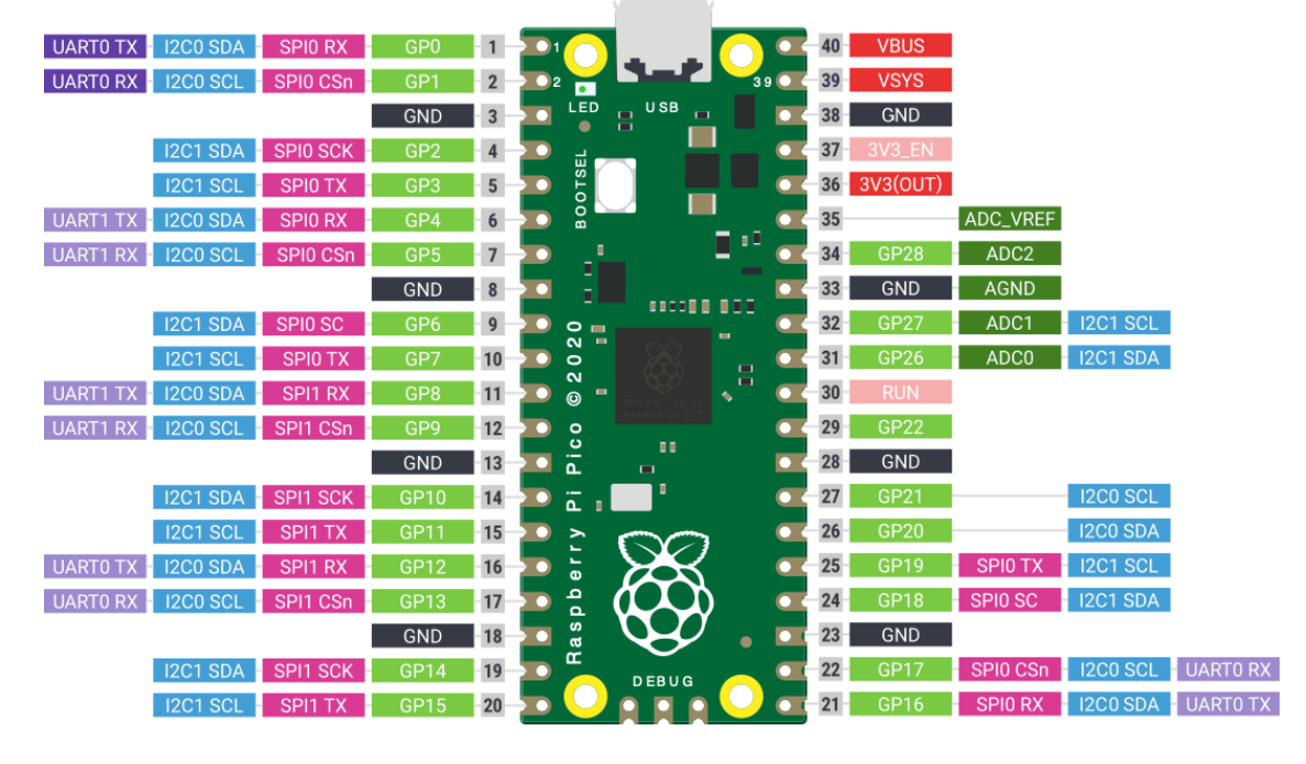
Step 14: Creating a script for the Pico Pi
Until now all of the tests in Unity have been done with keyboard controls. This is obviously not the end goal. To be able to control the virtual pinball with buttons we need to connect the Pico Pi with our PC. After the connection is established and the BOOTSEL button is held down for a few seconds a menu opens, which confirms the connection between computer and pico pi.
Now we need to write code and put it on the microcontroller. I decided to use micropython with thonny for this, as I already know a bit of Python. Below you can see the code with my comments explaining what it does.
import machine
import utime

# defining LED (for debugging)
led = machine.Pin(25, machine.Pin.OUT)

# array of all the pins I use
button_pins = [0, 1, 2, 3, 4, 5, 6]
buttons = []

for pin_num in button_pins:
    btn = machine.Pin(pin_num, machine.Pin.IN, machine.Pin.PULL_DOWN)
    buttons.append(btn)

# defining the pin of the plunger
plunger_sensor = machine.ADC(0)

print("Pico sends on COM Port...")

while True:
    # testing if connection is still there (I used it for debugging)
    led.toggle()

    # collecting all of the button states in an array
    # so that more than one can be used at once
    button_states = []
    for btn in buttons:
        button_states.append(str(btn.value()))

    # reading the plunger value
    raw_val = plunger_sensor.read_u16()
    mapped_val = int((raw_val / 65535) * 100)

    # creating a string out of the data
    # this way unity can later get the data quickly
    data_string = ",".join(button_states)
    final_message = "{},{}".format(data_string, mapped_val)

    # sending the data
    print(final_message)

    # adding a delay after each send, so that the program does not break instantly
    utime.sleep(0.02)
Step 15: Catching the sent inputs with unity
Now that the data that is put in by the buttons is being sent the last step is to get Unity to listen to those inputs and using them instead of the inputs from the keyboard. For this I created a new empty Unity component and created a new script with the help of Gemini. Basically what this code does is listen on a specified port for the datastring we created in the script before. If it is found the data from the string gets extracted and send to the other Unity scripts, who will basically tell the components what to do.
using System.Collections;
using System.Collections.Generic;
using UnityEngine;
using System.IO.Ports;
using System.Threading;
using System;

public class PicoInput : MonoBehaviour
{
    public string portName = "COM4";
    public int baudRate = 115200;

    SerialPort stream;
    Thread readThread;
    bool keepReading = false;

    [Header("Debug View")]
    public bool[] buttonStates = new bool[5];
    public int plungerValue = 0;

    void Start()
    {
        StartSerial();
    }

    void StartSerial()
    {
        try
        {
            stream = new SerialPort(portName, baudRate);
            stream.ReadTimeout = 50;
            stream.Open();

            keepReading = true;
            readThread = new Thread(ReadSerialLoop);
            readThread.Start();
            Debug.Log("Serial Port geöffnet: " + portName);
        }
        catch (System.Exception e)
        {
            Debug.LogError("Fehler beim Öffnen des Ports: " + e.Message);
        }
    }

    // Dieser Loop läuft im Hintergrund
    void ReadSerialLoop()
    {
        while (keepReading && stream.IsOpen)
        {
            try
            {
                string data = stream.ReadLine(); // Liest eine Zeile vom Pico
                ParseData(data);
            }
            catch (System.Exception)
            {
                // Timeouts sind normal, wenn gerade keine Daten kommen
            }
        }
    }

    void ParseData(string data)
    {
        string[] parts = data.Split(',');

        if (parts.Length == 6)
        {
            for (int i = 0; i < 5; i++)
            {
                buttonStates[i] = (parts[i] == "1");
            }

            int.TryParse(parts[5], out plungerValue);
        }
    }

    void OnApplicationQuit()
    {
        keepReading = false;
        if (readThread != null) readThread.Join(500);
        if (stream != null && stream.IsOpen) stream.Close();
    }
}
Step 16: The finishing touches and project reflection
The project required to use a lot of the techniques taught in the course, such as laser cutting, embedded programming and board design.
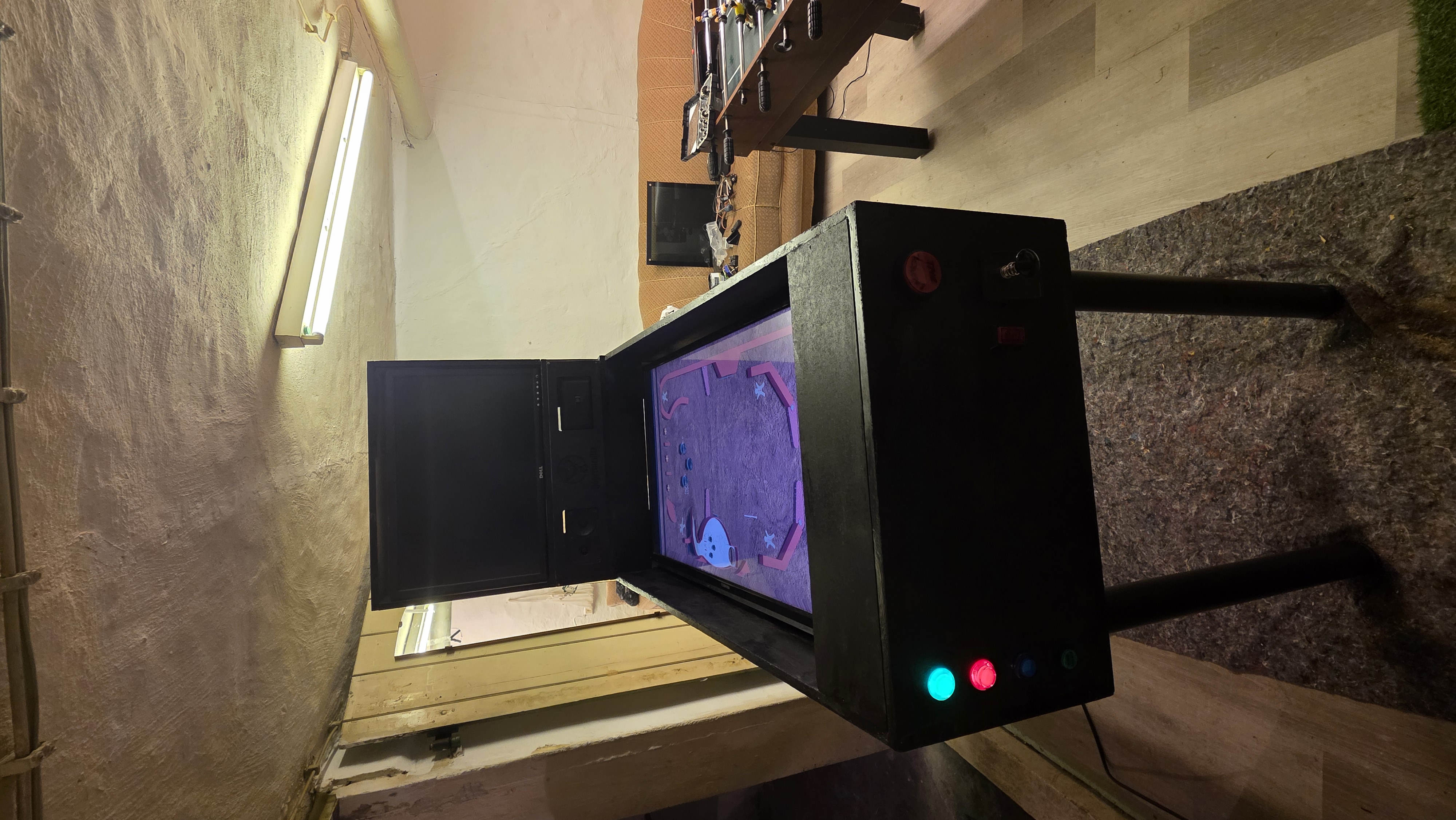
Now all that is left to do is turning the computer and TV on the project is working. I decided to paint the pinball machine black, as I have to paint it to later on put drawings on it. I also added a smaller piece of wood at the top monitor which has been designed with laser cutting. I will definitely keep on working on this project as it was a lot of fun, but still has so much room for improvement left. However I am very happy with how it turned out in the timeframe I had during this course.
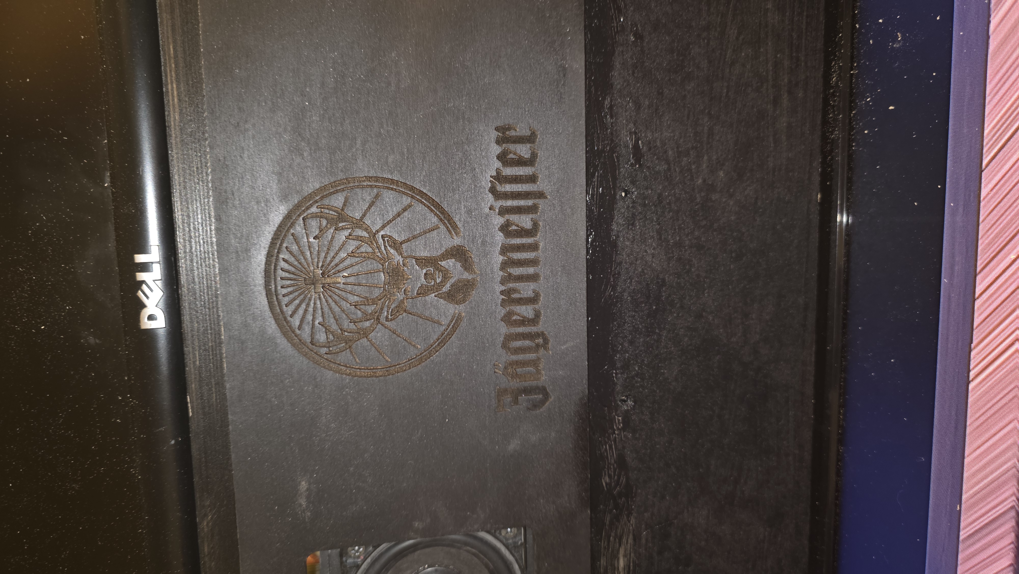
More pictures I had: